3D Workspace
Home
Assets
Affiliate Program
Sign up/Log in
?
Upgrade
DCC Bridge
Anonymous1773184216
03-10 23:18
Model Name
stormwater catchpit 3d model
Tags
machine
rendering
realistic
Prompt
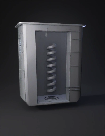
A highly detailed, professional 3D engineering render of a rectangular stormwater catchpit insert. The outer shell is a rectangular bucket, wider at the top and tapering slightly towards a flat bottom. It has a prominent flat rim (flange) around the top edge. Inside the bucket is a central helical baffle, resembling a thick spiral water slide, designed to force water to swirl in a vortex. The spiral connects to the inner walls of the rectangular bucket. At the exact center of the flat bottom floor, there is a single circular drain hole. The material is matte grey, textured recycled 3D-printed plastic. On one corner of the top rim, there is a small rectangular mounting bracket holding a small electronic sensor. Clean industrial design, architectural lighting, white background, precise geometry. Step 1: The Master Hull (The Drop-in Box) Create Sketch: Select the Top (XY) plane. Center Rectangle: Draw a rectangle snapping to the origin. Dimension it 670mm (Width) x 460mm (Height). Fillet: Use the Fillet tool on the 4 corners. Set the radius to R15 (15mm). Finish sketch. Extrude: Select the rectangle. Extrude downwards (Negative Z) by -350mm. Draft Angle: While still in the Extrude menu, set the Taper Angle to -3 degrees. (The bottom should be smaller than the top). Shell: Select the top flat face of your new solid body. Use the Shell command and set the inside thickness to 10mm. Result: You now have a hollow, tapered rectangular bucket. Step 2: The Top Flange (The Hanging Lip) Create Sketch: Select the very top edge/face of your bucket walls. Offset: Use the Offset tool on the outer edge. Offset it outward by 25mm. Finish Sketch. Extrude: Extrude this new 25mm rim downwards by 10mm. Ensure the operation is set to "Join". Result: Your bucket now has a lip so it doesn't fall through the street grate. Step 3: The Orifice & Silt Trap (The Flow Control) Create Sketch: Look inside your bucket and select the inside bottom floor. Center Circle: Draw a circle exactly in the center. Dimension it to 50mm diameter. Extrude Cut: Extrude this circle downwards through the bottom floor to create your main drain hole. Define the Silt Trap: You don't need to model anything new here, just remember that the bottom 50mm of elevation inside this bucket is mathematically reserved as your "Silt Trap" dead-zone. Step 4: The Vortex Baffle (The Hard Part) Because water naturally wants to fall straight down, we have to build walls to force it into a spiral. Central Core: Sketch on the inside bottom floor. Draw a circle 150mm in diameter in the center. Extrude it upwards by 250mm. (This is the central pillar the water will spin around). The Helix Path: Go to Create > Coil (in Fusion 360) or Helix/Spiral (in SolidWorks). Coil Settings: * Base face: Inside bottom floor. Center point: Origin (center of the drain). Diameter: 340mm (so it stays inside the walls). Type: Height and Pitch. Height: 200mm (Starts 50mm above the floor, ends 100mm from the top). Pitch: 100mm (This will give you 2 full spiral rotations). Section size/Profile: Make it a flat rectangular shelf, 50mm wide and 10mm thick. The Guide Walls: The spiral will leave empty gaps in the corners of your rectangular bucket (water will cheat and fall down the corners). Sketch flat vertical plates in those 4 corners that connect the square outer wall to the circular boundary of your spiral. Extrude them from the floor up to the top of the helix. Step 5: The High-Flow Bypass (The Safety Valve) Create Sketch: Select the inside face of the longest wall. Draw Rectangles: Draw three rectangles near the top, about 50mm down from the rim. Make them 100mm wide by 40mm high. Extrude Cut: Push them all the way through the wall. Result: If the 50mm hole at the bottom clogs, water spills out these top holes instead of flooding the street.
Detailed Info
Related Models
Enter invite code
Enter invite code to get credits!