3D Workspace
Home
Assets
Affiliate Program
Sign up/Log in
?
Upgrade
DCC Bridge
Anonymous1773988743
03-24 11:23
Model Name
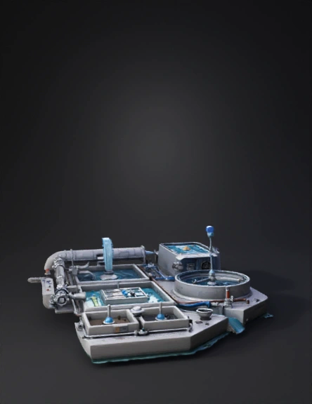
sewage treatment plant 3d model
Tags
architecture
simulation
realistic
Prompt
Create a highly detailed, realistic 3D animated model of a Sewage Treatment Plant (STP) with capacity 180–200 MLD (Pirana STP, Ahmedabad). The scene should be designed as a connected industrial facility with all units arranged logically and connected with pipes, showing smooth water flow from start to end. -------------------------------------------------- SCENE SETUP: • 3D isometric or slightly angled top view (30–45 degrees) • Smart city industrial environment • Realistic materials: concrete tanks, metallic pipes, water textures • Bright daylight with soft shadows • Smooth animation of flowing water and moving components -------------------------------------------------- MAIN WATER FLOW (LEFT TO RIGHT): 1. Inlet & Collection - A single rising main pump bringing sewage from underground pipelines - Large inlet pipe entering the plant - Inlet Chamber (180–200 MLD) Visual detail: - Show label: “Flow divided into 3 streams (~67.5 MLD each)” (do NOT physically split) - Add floating sensor icons displaying: • BOD (Biochemical Oxygen Demand) • COD (Chemical Oxygen Demand) • TSS (Total Suspended Solids) • TKN (Total Kjeldahl Nitrogen) • pH (Potential of Hydrogen) -------------------------------------------------- 2. Screen Chamber - Step screen (5 mm) with moving mechanical bars - Water flowing through screen - Solid waste slowly moving upward into a hopper - Motor control panel beside unit - Screen cleaning flush water spray animation -------------------------------------------------- 3. Grit Chamber - Rectangular or circular tank - Water entering and rotating (centrifugal motion) - Sand and grit visibly settling at bottom - Clean water flowing out from top -------------------------------------------------- 4. Parshall Flume - Narrow open channel section - Water accelerating through flume - Label: “Flow Measurement (MLD, m³/hour)” - Add subtle measurement markers -------------------------------------------------- 5. Equalization Tank - Large tank with gentle mixing - Slight water movement showing balancing effect - Pipes connecting smoothly to next stage -------------------------------------------------- 6. Primary Clarifier - Circular sedimentation tank with rotating scraper arm - Sludge settling at bottom - Oil layer floating on top IMPORTANT VISUAL: - Clearly show: • Anaerobic zone (darker lower layer) • Initial aerobic zone (upper lighter layer) -------------------------------------------------- 7. Aeration Tank (CORE ANIMATION ZONE) - Large rectangular tank - Strong aeration bubbles rising from diffusers Label: “ASP (Activated Sludge Process) + IFAS (Integrated Fixed Film Activated Sludge)” IMPORTANT DETAILS: - IFAS media cages placed in center of tank - Show bacteria layer attached to media Blower Room: - Separate room with large blowers - Pipes carrying air into aeration tank - Animated airflow or bubbles entering water -------------------------------------------------- 8. Secondary Clarifier - Circular tank with rotating arm Show separation clearly: TOP: - Clean water flowing out BOTTOM: - Sludge settling IMPORTANT PIPELINES: • RAS (Return Activated Sludge) - Blue colored pipe - Flowing back to aeration tank • WAS (Waste Activated Sludge) - Brown colored pipe - Flowing downward to sludge treatment -------------------------------------------------- 9. Tertiary Treatment Cloth Media Filter: - Compact filter unit - Water passing through layered media ↓ Chlorination Tank: - Chemical dosing system - Mixing effect -------------------------------------------------- 10. Final Discharge - Clean blue-green water flowing out into river or reuse channel Label: “GPCB / NGT Compliant Water” -------------------------------------------------- SLUDGE LINE (BOTTOM FLOW): - Merge sludge from Primary and Secondary Clarifier ↓ Thickener: - Sludge becoming denser - Water separating out ↓ Digester: - Closed tank - Optional gas dome (biogas) ↓ Final Output: - Thick sludge cake - Label: “Used as Manure / Fertilizer” IMPORTANT: Do NOT include screw press -------------------------------------------------- CONNECTIONS: • All units must be connected with visible pipelines • Smooth animated flow of water between stages • Use arrows or flow direction indicators • Maintain logical spacing between units -------------------------------------------------- COLOR CODING: • Blue → Water flow • Green → Treated water • Brown → Sludge and WAS pipeline • Blue pipe → RAS return • Grey/metal → machinery • Purple glow → sensors/data points -------------------------------------------------- ANIMATION STYLE: • Smooth water flow animation throughout system • Rotating clarifier arms • Moving screen mechanism • Bubbling aeration tank • Flowing sludge in pipelines • Slight camera pan across plant -------------------------------------------------- FINAL REQUIREMENTS: • Make the entire system look connected and continuous • Maintain industrial realism • Ensure clarity of each stage • Highlight flow movement visually • Make it attractive, professional, and presentation-ready
Detailed Info
Related Models
Enter invite code
Enter invite code to get credits!