3D Workspace
Home
Assets
Affiliate Program
Sign up/Log in
?
Upgrade
DCC Bridge
Anonymous1765184510
12-08 09:33
Model Name
mechanical base 3d model
Tags
machine
3d printing
realistic
Prompt
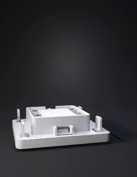
Create a precise, engineering-grade 3D model of a palm-side servo mount for the ME-US ME-X8 micro servo, placed exactly in the same orientation as the reference image, assuming it is mounted on the LEFT palm. ■ Orientation Definition (critical) - The model is positioned as if resting on the LEFT hand. - In this orientation: • Left side of the image = Thumb side. • Right side of the image = Little-finger side. • Top of the image = Forward direction (toward the fingers). • Bottom of the image = Wrist direction. • Front face of the servo = Facing the palm. - All openings, holes, and directions must follow this coordinate definition exactly. ■ Base Plate - Rectangular base plate: 60 mm (width, thumb-to-little-finger) × 30 mm (height, finger-to-wrist) × 2 mm thickness. - Rounded corners with a radius of approximately 5 mm. - Two Velcro strap loops located at the far left and far right edges: • Internal opening: 20 mm width × 2.5 mm height. • Wall thickness: 1.5 mm. • Loops open upward, toward the palm side. - Two reinforcement ribs on the backside (opposite the palm side): • 0.8 mm thickness. • Running along the forward–wrist axis. ■ Servo Holder (Tray) - Internal clearance dimensions for ME-X8: 23.6 × 12.6 × 27.6 mm. - Servo tray is offset 15 mm toward the thumb side (image-left direction) from plate center. - Servo orientation: • Output shaft faces forward (toward the fingers). • Servo horn faces the thumb side (image-left). ■ Screw Mounts (M2 holes on BOTH sides) - Provide two symmetric M2 screw holes on BOTH the thumb side wall and the little-finger side wall. - Hole details (per side): • Two holes aligned horizontally (left ↔ right direction). • Hole diameter: 2.2 mm. • Center-to-center spacing: 16 mm. • Shallow screw-head recess: 4 mm diameter × 1 mm depth. - IMPORTANT: These holes MUST run horizontally from thumb side toward little-finger side (image-left → image-right), not front-to-back. ■ Cable Relief Slot - A cable exit slot located on the wrist side (image-bottom), at the lower back corner of the tray. - Slot size: approximately 6 mm width × 3 mm height. - Opening must face the wrist direction only (image-down), NOT upward. ■ Manufacturing Requirements - Single, manifold, watertight mesh. - Real-world millimeter scale. - FDM-friendly geometry: • No overhangs beyond 45°. • Structural areas 2 mm thickness minimum. - Add 0.5 mm fillets to interior corners of the servo tray. ■ Style - Clean mechanical geometry. - No textures or decoration.
Detailed Info
Related Models
Enter invite code
Enter invite code to get credits!