3D Workspace
Home
Assets
Affiliate Program
Sign up/Log in
?
Upgrade
DCC Bridge
Anonymous1773828399
03-19 17:09
Model Name
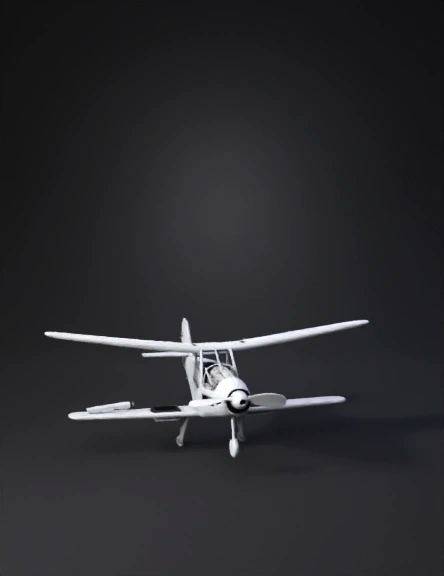
fixed-wing drone 3d model
Tags
vehicle
3d printing
realistic
Prompt
Generate a complete 3D CAD model of a fixed-wing UAV optimised for 3D printing in ABS plastic. The design is a conventional tractor-propeller configuration with a high-wing or mid-wing layout, cruciform tail (separate horizontal and vertical stabilisers), and a monocoque fuselage. All geometry must be parametric, hollow-shelled for printing, and structurally self-consistent. GLOBAL DIMENSIONS - Total wingspan: 1200 mm - Fuselage length: 1000 mm - Overall height: ~220 mm (fuselage + vertical tail) - Material: ABS plastic, 1.5–2.0 mm shell walls - Print orientation: Split fuselage (top/bottom halves) + detachable wings FUSELAGE - Length: 1000 mm - Cross-section: Rounded rectangular, 80 mm wide × 70 mm tall at widest point - Nose: Rounded ogive nose, 120 mm long, spinner clearance ⌀60 mm - Motor mount: Circular bulkhead at nose, ⌀28 mm bore, 4× M3 bolt pattern on 19 mm PCD - Cockpit/bay hatch: Removable top hatch, 180 mm × 60 mm, at station 150–330 mm from nose - Battery bay: Internal cavity 140 mm × 45 mm × 35 mm at station 300–440 mm - Electronics bay: Cavity 90 mm × 50 mm × 30 mm at station 440–530 mm - Wing saddle: Rectangular cutout + 8 mm carbon tube socket pair, at 380 mm from nose (38% fuselage length) - Tail boom taper: Fuselage tapers from 80 mm wide at 600 mm station to 30 mm at tail, elliptical cross-section - Wall thickness: 2.0 mm outer shell; 3 internal formers at stations 150 mm, 400 mm, 650 mm - CG datum: Mark at 350 mm from nose for balance reference MAIN WINGS (×2, mirrored) - Total span: 1200 mm (600 mm per semi-span) - Root chord: 220 mm | Tip chord: 130 mm (taper ratio 0.59) - Mean aerodynamic chord: 180 mm | Wing area: 0.24 m² | Aspect ratio: 6.0 - Sweep: 0° at quarter-chord (straight leading edge, taper on trailing edge) - Dihedral: 3° per semi-wing - Incidence: 2° positive at root - Washout: −2° twist at tip (linear interpolation) - Airfoil: NACA 2412 at root, NACA 2408 at tip - Spar socket: ⌀8 mm tube channel at 25% chord from LE, running full semi-span - Skin: 1.5 mm ABS shell, 3 ribs per semi-span at 150 mm, 350 mm, 530 mm from root - Tip: Blunt elliptical rounding, 15 mm radius - Mount: Root rib with 2× ⌀8 mm rod sockets + 2× M3 bolt holes to fuselage saddle AILERONS (×2, one per wing) - Spanwise: 65%–95% semi-span (390–570 mm from root) - Chord: 25% local chord (~40 mm mid-aileron) - Hinge at 75% chord | Deflection: ±20° - Servo pocket: 22 mm × 12 mm in lower wing skin at 70% semi-span - Pushrod exit: 1.5 mm hole at hinge line, 2 mm from skin HORIZONTAL STABILISER + ELEVATOR - Span: 360 mm (180 mm per side) | Root chord: 130 mm | Tip chord: 90 mm - Airfoil: NACA 0009 (symmetric) | Area: 0.043 m² - Setting angle: −1.5° | Moment arm: 550 mm from wing MAC - Tail volume coefficient: Vh = 0.49 - Mount: Integral with tail boom, 2× M3 bolt attachment - Elevator: 35% chord (38–46 mm), full span, split at centreline, deflection +25°/−20° - Hinge: 2× M2 pin hinges per side VERTICAL STABILISER + RUDDER - Height: 140 mm | Root chord: 170 mm | Tip chord: 100 mm - Airfoil: NACA 0009 (symmetric) | Area: 0.0189 m² - LE sweep: 25° | Mounted atop fuselage at 970 mm from nose - Rudder: 35% chord (45–60 mm), full height (140 mm), deflection ±25° PROPULSION & MOTOR MOUNT - Configuration: Tractor (puller), front-mounted - Motor mount bore: ⌀28 mm cylindrical boss, 15 mm deep into nose bulkhead - Bolt pattern: 4× M3 holes on 19 mm PCD (standard 2212 outrunner) - Spinner clearance: ⌀60 mm at nose face - Prop arc clearance: nose to wing LE ≥ 220 mm - Motor assumed: 2212 1400KV brushless outrunner - Propeller: 8×4.5 inch (⌀203 mm); ground clearance ≥ 40 mm with gear LANDING GEAR - Type: Fixed tricycle (2× main + 1× nose wheel) - Main gear: 350 mm from nose, 180 mm lateral spacing, 65 mm leg length - Nose gear: 80 mm from nose, centreline, 55 mm leg, castering - Wheel diameter: ⌀40 mm, printed hub with TPU tyre option - Attachment: M3 bolt pockets into fuselage lower keel MASS & CG - ABS airframe: ~460 g | Electronics: ~180 g | Battery: ~170 g | Misc: ~90 g - MTOW: ~900 g - Target CG: 30% MAC = 54 mm from wing LE at root, ~340 mm from nose - Static margin: 12% MAC PRINT & ASSEMBLY NOTES - Fuselage splits longitudinally top/bottom; wings detach at root - Wall thickness: 2.0 mm fuselage, 1.5 mm wing skins, 2.5 mm spar tube walls - Suggested infill: 15% gyroid (fuselage), 10% (wing panels) - Spar: ⌀8 mm carbon fibre tube sockets only in CAD (not printed) - Servo wiring conduit: 4 mm diameter channel along wing lower surface and fuselage floor - Control surface hinges: 2 mm pin knuckle geometry (two-part, print in place) - Battery connector slot: XT30 cutout 18 mm × 10 mm at battery bay front face - Access hatches: friction-fit or M2 screw retention FLIGHT PERFORMANCE TARGETS (for reference/validation) - Stall speed: 7.6 m/s | Cruise: 10–13 m/s | Max level: ~18 m/s - Wing loading: 36.8 N/m² | Estimated endurance: 18–22 min on 3S 2200mAh - Reynolds number at cruise: ~135,000
Detailed Info
Related Models
Enter invite code
Enter invite code to get credits!
 Anonymous1773828399


 Anonymous1773828399