3D Workspace
Home
Assets
Affiliate Program
Sign up/Log in
?
Upgrade
DCC Bridge
Anonymous1768929358
04-04 08:05
Model Name
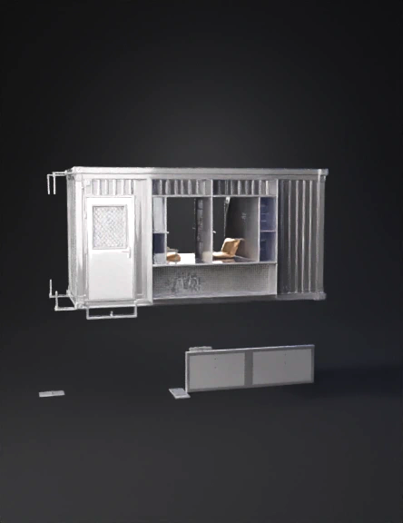
prefab office cabin 3d model
Tags
architecture
simulation
realistic
Input
Prompt
i want you to make 3D view of this sample Create a professional industrial fabrication engineering drawing sheet for a portable prefab site office / steel cabin enclosure, based strictly on the provided front view and top view layout. The drawing must look like a real shop fabrication / manufacturing / CAD technical blueprint and must be dimensionally consistent across all views. REQUIRED OUTPUT STYLE: Black and white technical engineering drawing Clean CAD linework Fabrication drafting style Mechanical / architectural shop drawing sheet Professional blueprint presentation No artistic rendering, no painterly effects, no soft concept art Highly precise, neat, orthographic and fabrication-oriented REQUIRED SHEET LAYOUT: Include all of the following on a single technical drawing sheet: FRONT ELEVATION PLAN VIEW (TOP DOWN) RIGHT SIDE ELEVATION ISOMETRIC 3D FABRICATION VIEW DETAIL CALLOUTS BILL OF MATERIALS (BOM) GENERAL NOTES TITLE BLOCK PROJECT TYPE: Portable Prefabricated Steel Office Cabin / Industrial Site Office Enclosure GEOMETRY / FORM: Rectangular cabin enclosure Flat roof with slight slope for drainage Roof has overhang / projection on all sides Steel framed modular structure Raised base frame / skid base appearance Exterior designed as a fabricated portable cabin FRONT ELEVATION REQUIREMENTS: Match the given front concept with these visible elements: Left-side single steel access door Door must include: hinges lockset / handle small rectangular mesh or vent vision panel Next to the door, include a large front glazed window system Window area divided into structural mullions / vertical frame members Front glazing should show: office desk inside office chair monitor / workstation On the far-right front bay, include a narrow vertical storage / shelving visible zone Lower front wall below glazing should include a solid perforated / mesh / cladded panel Frame members should appear structural and fabrication-ready PLAN VIEW (TOP DOWN) REQUIREMENTS: Create the plan view based on the supplied top layout: Rectangular footprint Entry door located at the front-left Main office desk and chair visible inside Large central open office zone Right side internal storage / shelving / file rack area Wall thickness and frame lines must be shown Door swing must be shown clearly Internal furniture should match the isometric/front arrangement Any side-mounted external utility box / AC / vent shown if visible in reference RIGHT SIDE ELEVATION: Add a clean side view that is consistent with: flat/sloped roof edge plain solid side wall panels base skirting / base frame structural vertical posts optional external mounted box / vent / AC unit if consistent with plan ISOMETRIC 3D FABRICATION VIEW: Create a clean professional isometric 3D view of the same exact enclosure: Must match the front and top views exactly Show: steel frame structure front door front windows lower front perforated panel side wall panels roof fascia and overhang base frame / skids Isometric view should look like a fabrication-ready product visualization Interior office setup can be lightly visible through glazing Keep it technical and realistic, not decorative STRUCTURAL / FABRICATION DETAILING: Add realistic fabrication details suitable for shop drawing presentation: Corner steel posts Roof edge section Base frame section Door frame fixing Window mullion section Lower front panel fixing Wall panel sandwich / sheet fixing detail Roof panel to frame connection Base plate / support detail Include labeled detail bubbles such as: Detail A – Base Frame Joint Detail B – Door Frame Fixing Detail C – Window Mullion Section Detail D – Lower Panel Section Detail E – Roof Edge / Fascia Section MATERIAL / FABRICATION ASSUMPTIONS: Use realistic industrial portable cabin materials: Primary frame: RHS / HSS steel sections Base frame: fabricated steel channel / RHS Wall skin: insulated steel sheet / panelized cladding Front lower panel: perforated metal / expanded mesh / decorative cladding panel Window frames: aluminum or steel framed glazing Door: steel flush fabricated door Roof: insulated sandwich roof panel or sheeted roof assembly BILL OF MATERIALS (BOM): Add a neat BOM table including realistic items such as: Main corner posts Roof perimeter frame Base frame Steel door Door hardware Front glazing frame Glass panels Lower front decorative / perforated panel Side wall panel sheets Roof panel Internal shelving Base skirting / trim Add columns: Item No. Description Qty Material / Spec DIMENSIONS: This is critical: Add dimensions in millimeters Dimensions must be aligned and technically readable Show: overall width overall depth overall height door width and height glazing width and height panel heights roof overhang internal storage zone width All views must be dimensionally consistent No random dimensions No contradictory geometry GENERAL NOTES: Add realistic fabrication notes such as: All dimensions are in millimeters unless noted otherwise Verify dimensions at site before fabrication All steel members to be properly welded and finished Provide anti-rust coating / primer before final finish Ensure all openings are aligned with structural frame Glazing and panel fixing to be as per approved shop practice Roof slope to ensure proper rainwater drainage
Detailed Info
Related Models
Enter invite code
Enter invite code to get credits!